Propagation of Radio Waves through the ISM
- Draine Ch 11
Propagation of Radio Waves through ISM
Propagating radio waves interact with the plasma particles, and therefore, the velocity of the wave propagation is slower than would be the case in a vacuum. I.e., the speed of light is slower when it has to move through stuff!
In this lecture, we’ll discuss how to calculate the dispersion measure and the rotation measure of electromagnetic radiation propagating through the ISM, and then how to use them to learn about the properties of the intervening ISM.
Dispersion relation for cold plasmas
Let wavenumber be $$ k = \frac{2 \pi}{\lambda}, $$ and angular frequency be related to linear frequency by $$ \nu = \frac{\omega}{2\pi}. $$
Electromagnetic waves propagating through a cold plasma with electron density \(n_e\) must satisfy the dispersion relation $$ k^2 c^2 = \omega^2 - \omega_p $$ where $$ \omega_p = \left ( \frac{4 \pi n_e e^2}{m_e} \right)^{1/2} = 5.641 \times 10^4 \sqrt{\frac{n_e}{\mathrm{cm}^{-3}}} \; \mathrm{s}^{-1} $$ is the plasma frequency. If we’re in a vacuum, no dispersion!
There’s something called the phase velocity, which is the propagation of the surface of constant phase: $$ v_\mathrm{phase} = \frac{\omega}{k} = \frac{c}{\sqrt{1 - (\omega_p/\omega)^2)}} > c $$ Confusingly, this velocity can be faster than the speed of light! But this is just a “mirage”–these don’t carry any energy. Wikipedia helps with the visualizations here a lot. They are important for considering polarization, as we’ll see with Faraday rotation.
We are more concerned with the group velocity $$ v_g(\omega) = \frac{d \omega}{d k} $$ which, in a plasma, is $$ v_g = c \left ( 1 - \frac{\omega_p^2}{\omega^2} \right)^{1/2}. $$ The group velocity is the speed at which information (energy) can be transmitted, and indeed, \(v_g < c\).
Dispersion Measure
- Time delay of radiation as a function of frequency depends on intervening electron density
Now let’s consider some astronomical object that can emit a well-defined pulse of radiation, like a pulsar. Let \(L\) be the distance to the pulsar, and assume that \(t=0\) corresponds to the time of emission. As a function of frequency, what is the arrival time of the emission?
Let’s break the path up into small segments, each with length \(dL\). Using the group velocity for a given frequency, how long does it take radiation of that frequency to traverse \(dL\)? Since velocity is distance over time, we can just divide \(dL\) by the group velocity to get \(dt\) $$ dt = \frac{dL}{v_g(\omega)} $$ and $$ t_\mathrm{arrival} = \int_0^L \frac{dL}{v_g(\omega)} $$ We can plug in \(v_g(\omega)\), but then we get a tricky term denominator. Let’s do a Taylor expansion of \(f(\omega) = 1/v_g(\omega)\) around \(\omega\), and see if we can arrive at an expression that is friendlier to integrate.
To first order, the Taylor series expanded around \(x=a\) will look like $$ f(x) \approx f(a) + f^\prime(a)(x - a). $$ This is just a constant plus a linear term (draw a graph). One of the assumptions behind an accurate Taylor expansion is that the perturbation away from the reference point \(a\) is small. To ensure this, we can rewrite \(f(\omega)\) as $$ f(x) = \frac{1}{c}(1 - x^2)^{-1/2} $$ where \(x = \omega_p / \omega\). From the previous discussion around plasma frequency, we already pointed out that \(0 \lesssim x \ll 1\), so we will Taylor expand in terms of \(x\) about the point \(a = 0 \), and then resubstitute in for \(x\). This yields $$ f(\omega) \approx \frac{1}{c} \left ( 1 + \frac{1}{2} \frac{\omega_p^2}{\omega^2}\right) $$ and allows us to rephrase the integral as $$ t_\mathrm{arrival} = \int_0^L \frac{dL}{c} \left ( 1 + \frac{1}{2} \frac{\omega_p^2}{\omega^2}\right) $$
$$ t_\mathrm{arrival} = \frac{L}{c} + \frac{1}{2 c \omega^2} \int_0^L \omega_p^2 d L. $$
Let’s rewrite the plasma frequency \(\omega_p\) in terms of the electron density \(n_e\), and define the dispersion measure to be $$ DM = \int_0^L n_e d L $$ such that we have $$ t_\mathrm{arrival} = \frac{L}{c} + \frac{e^2}{2 \pi m_e c} \frac{1}{\nu^2} DM $$ or, evaluating the constants, $$ t_\mathrm{arrival} = \frac{L}{c} + 4.146\times10^{-3} \left ( \frac{\nu}{\mathrm{GHz}} \right)^{-2} \frac{DM}{\mathrm{cm}^{-3}\;\mathrm{pc}}\;\mathrm{s} $$
A typical DM for a pulsar 3 kpc away might be \(DM \approx 10^2\;\mathrm{cm}^{-3}\;\mathrm{pc} \), which, at an observing frequency of 1 GHz, would yield a delay of 0.4 s after traveling \(10^4\) years.
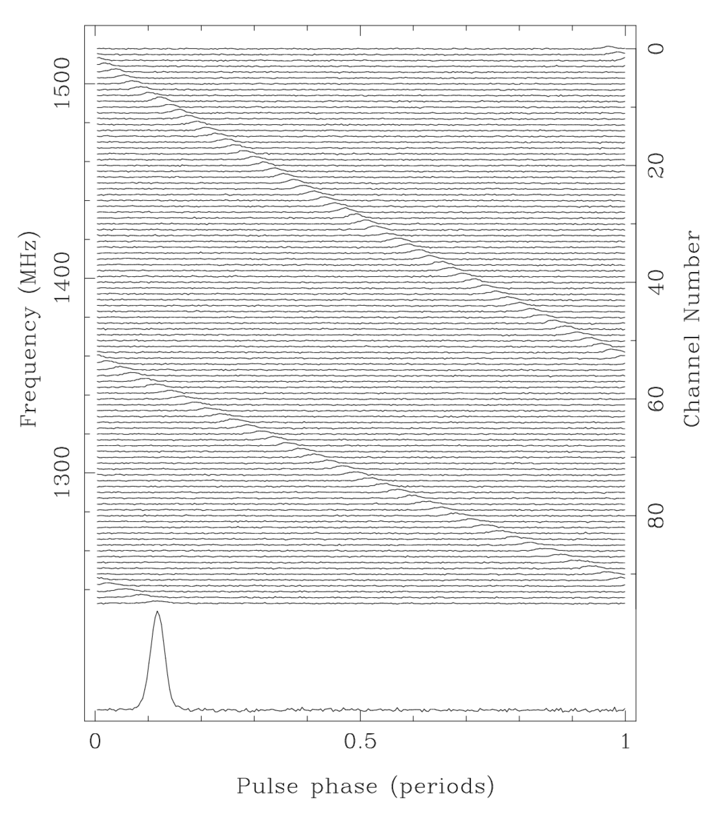
On it’s own, this isn’t very useful to us, because we don’t know when \(t=0\) was. But what we can exploit is the frequency dependence of the arrival time, \(t_\mathrm{arrival} \propto \mathrm{const} + \nu^{-2}\). This means that lower frequencies arrive later, such that the pulse is “dispersed.” We can compare the relative arrival times and compare this to $$ \frac{d t_\mathrm{arrival}}{d \nu} = - \frac{e^2}{\pi m_e c\nu^3} DM $$ calculate the DM and thus the integrated electron density.

Observations of (at least three pulses) of a pulsar, showing that lower frequency emission takes longer to arrive. The change in arrival time as a function of frequency can be used to calculate the dispersion measure, and thus the intervening electron density. Credit: caspar.astro.berkeley.edu
Some helpful commentary on dispersion measures in this pedagogical note by S. Kulkarni.
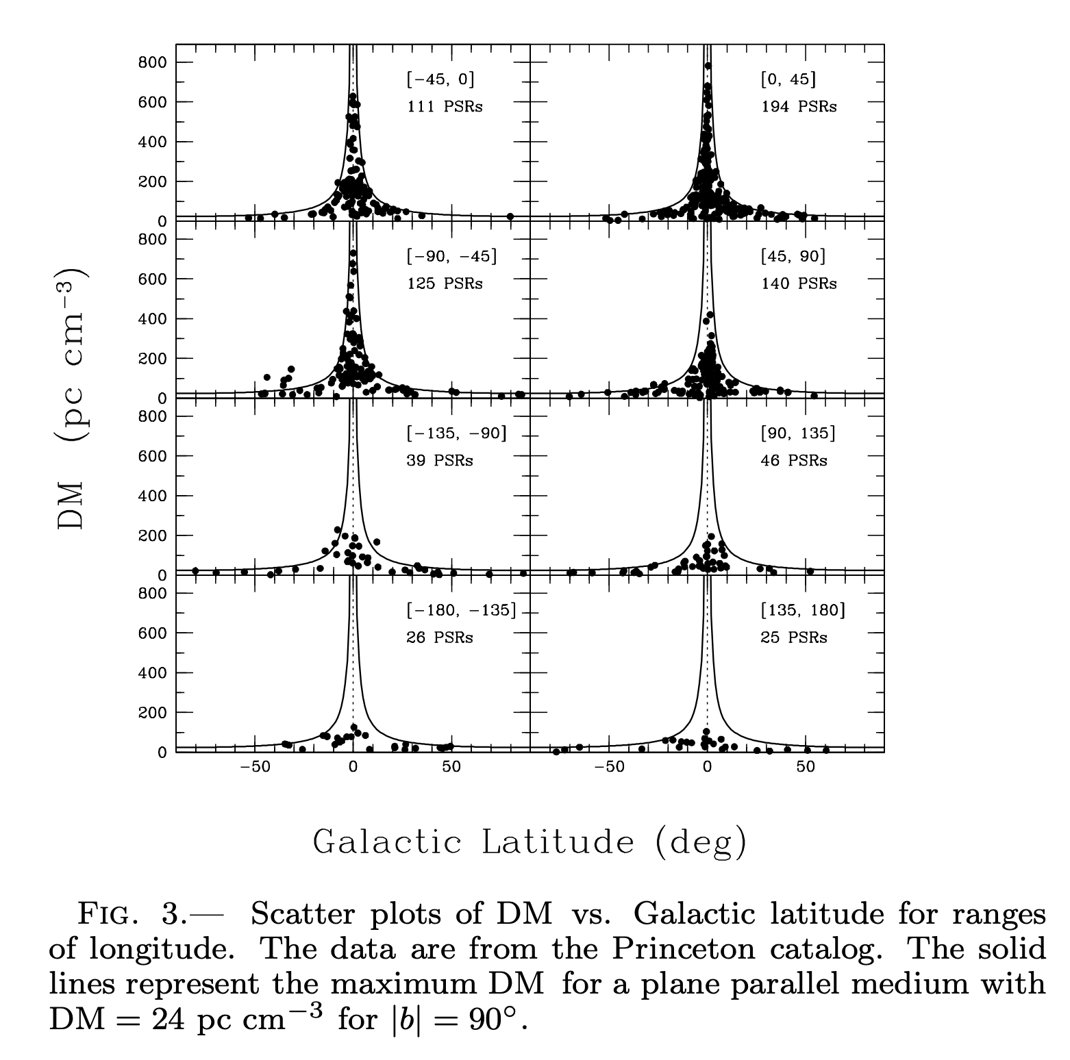
If you do this for many hundreds of pulsars, and you have reasonable estimates of their \(L\) from other data, then you can build up a 3D model of the electron density of the galaxy, probed by these pencil beam measurements. For example, take a look at these plots of dispersion measure vs. pulsar position complied by Cordes and Lazio 2003.

Credit: Cordes and Lazio 2003, arXiv:astro-ph/0301598

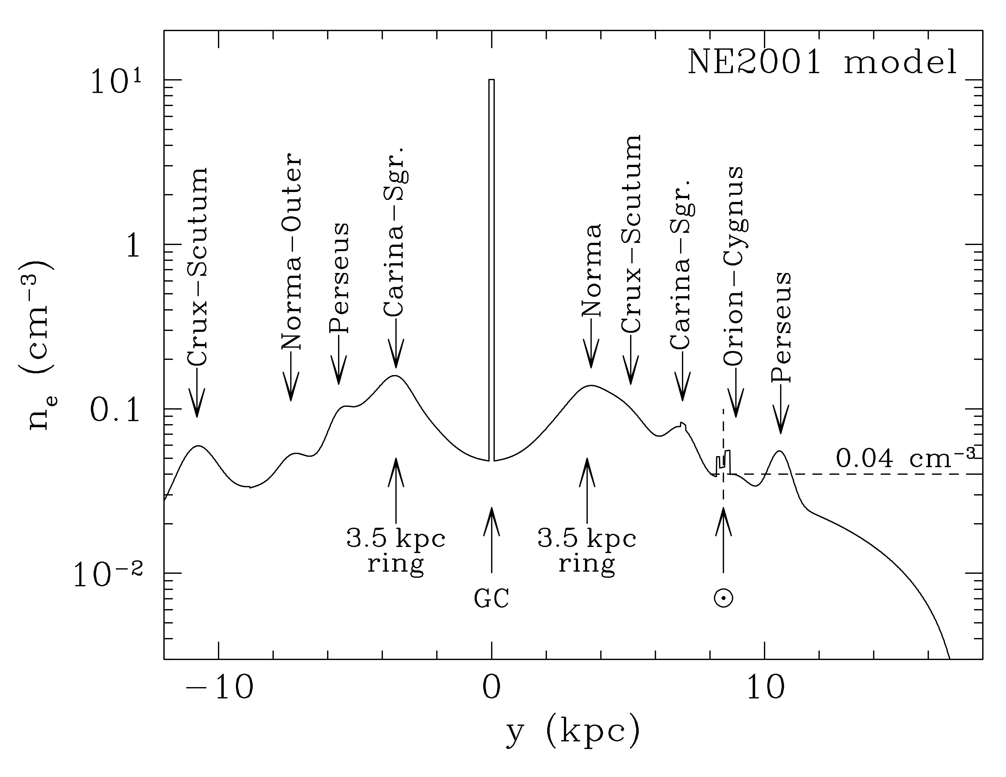
The electron density \(n_e\) at the Galactic midplane on a line passing through the Galactic Center (GC) and the Sun, as estimated using the NE2001 model of Cordes and Lazio. Credit: Draine Figure 11.2
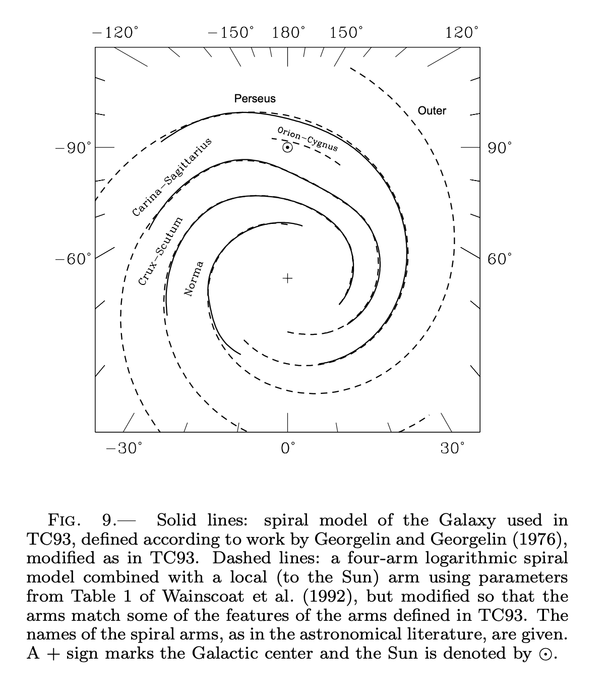
Put together into an estimate of the Galaxy’s spiral arm structure: Credit: Cordes and Lazio 2003, arXiv:astro-ph/0301598
Traces things like
- enhanced electron densities from material that has been shock-compressed by SNe explosions
- underdensities of electrons in “local hot bubble,” also caused by SNe
- other SNe remnants, too
- GC region has enhanced electron density
- electron density tapering off with distance from midplane, with scale height of ~ 1 or 2 kpc.
Faraday rotation
- polarization of light depends on the the presence of a magnetic field along intervening line of sight
Define the cyclotron frequency $$ \omega_B = \frac{e B_{||}}{m_e c} $$ where \( B_{||}\) is the component of the magnetic field parallel to the direction of propagation. The dispersion relation for circularly polarized waves in cold plasma is $$ k^2 c^2 = \omega^2 - \frac{\omega_p^2}{1 \pm \frac{\omega_B}{\omega}} $$ where the \(\pm\) applies to right/left circular polarization. When we calculate the phase velocity (using similar Taylor expansion tricks for \(\omega_B / \omega \ll 1\) and \(\omega_p / \omega \ll 1\)), we see $$ v_\mathrm{phase}(\omega) = \frac{\omega}{k(\omega)} \approx c \left [ 1 + \frac{1}{2}\frac{\omega_p^2}{\omega^2} \mp \frac{1}{2}\frac{\omega_p^2 \omega_B}{\omega^3} \right]. $$ What’s interesting about this is that the right/left circular polarization modes differ in phase velocity and wavenumber $$ v_{\mathrm{phase},L} - v_{\mathrm{phase},R} = \frac{4 \pi e^3}{m_e^2} \frac{n_e B_{||}}{\omega^3}. $$ and $$ \Delta k = k_R - k_L = \frac{4 \pi e^3}{m_e^2 c^2} \frac{n_e B_{||}}{\omega^2} $$ You can decompose even pure linear polarization into equal amounts of left and right circular polarized light. If the light propagates through a magnetized plasma, it will have its modes propagate at different phase velocities, which means after propagating some distance \(L\), the two waves will differ in phase by \(L \Delta k\).
Faraday rotation, demonstrating how the angle of linear polarization is rotated when propagating through a magnetized plasma. Credit: Wikipedia, DrBob.
When you recompose this back into a linear polarization, you see that the angle of polarization has rotated clockwise relative to its original angle by $$ \Phi = \frac{1}{2} \int_0^L \Delta k \; d L = \int_0^L \frac{\omega_p^2 \omega_B}{2 c \omega^2} d L $$ $$ \Phi = \frac{e^3}{2 \pi m_e^2 c^2}\frac{1}{\nu^2} \int_0^L n_e B_{||} \; dL $$ $$ \Phi = RM \; \lambda^2 $$ where we define the rotation measure as $$ RM = \frac{1}{2 \pi} \frac{e^3}{m_e^2 c^4} \int_0^L n_e B_{||} \; dL $$ $$ RM = 8.120 \times 10^{-5} \int_0^L n_e B_{||} \; dL \frac{\mathrm{rad}\;\mathrm{cm}^{-2}}{\mathrm{cm}^{-3}\; \mu G \; \mathrm{pc}}. $$ I.e., the rotation measure is the integral of the electron density times the parallel component of the magnetic field along the line of sight. In analogy to the dispersion measure, we don’t know the starting point of the linear polarization angle, but, because the change in rotation angle is wavelength-dependent, by measureing the linear polarization angles at two different wavelengths \(\lambda_1\) and \(\lambda_2\), we can calculate the rotation measure $$ RM = \frac{\Phi_2 - \Phi_1}{\lambda_2^2 - \lambda_1^2}. $$
Putting it all together
If you measure both the RM and DM, you can put them together to calculate the electron density-weighted mean value of the line of sight magnetic field $$ \langle B_{||} \rangle = \frac{2 \pi m_e^2 c^4}{e^3} \frac{RM}{DM}. $$ Background sources like AGNs and pulsars are good for this type of calculation because they are in general strongly linearly polarized (from synchrotron radiation). Putting this together for many sightlines, Han et al. 2006 concludes magnetic field in Galactic disk follows spiral structure, but reverses direction from spiral arms to interarm regions.
Other propagation effects
We don’t have time to cover these, unfortunately, but be aware that we can also study
- refraction: “clumpiness” of ISM from electron density variations
- scintillation: “twinkling” helps track turbulence in the ISM
- extreme brightening events: chance refraction through blobs in ISM, possibly from shells of SNe
More information provided in Draine Chs. 11.4 - 11.7